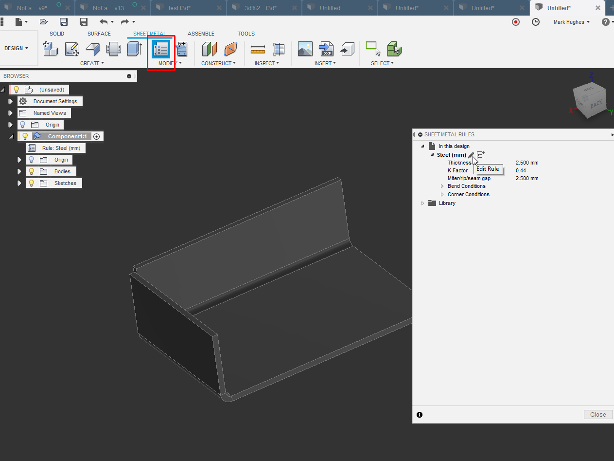
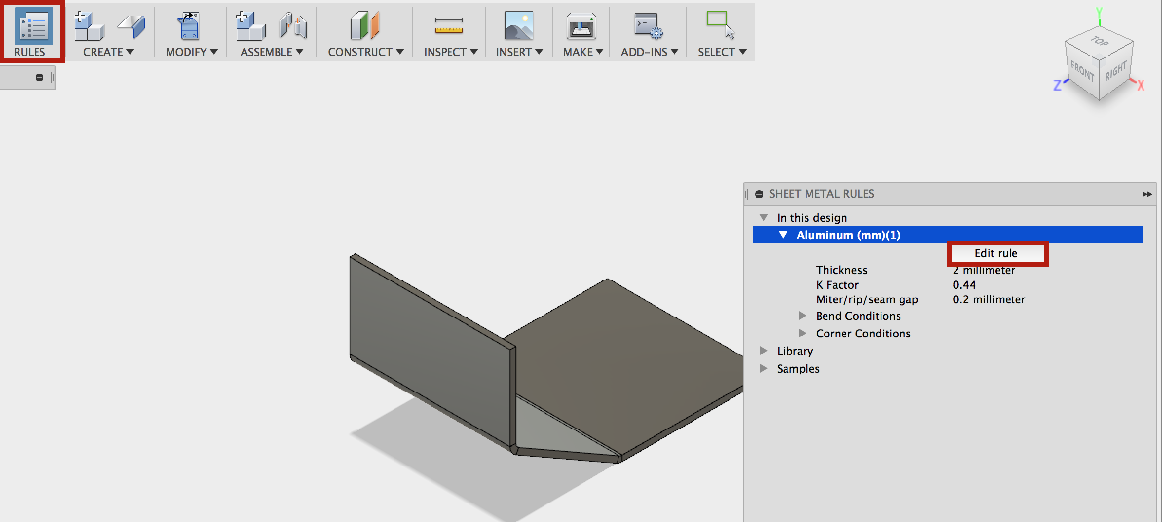
Our intention is to provide you a simple way to build your library by providing you with a handful of starter rules you can copy edit and save to your library.
Changing sheet metal thickness in fusion 360.
So i opened my machinery handbook and flipped to the gauge table and bend allowance chart.
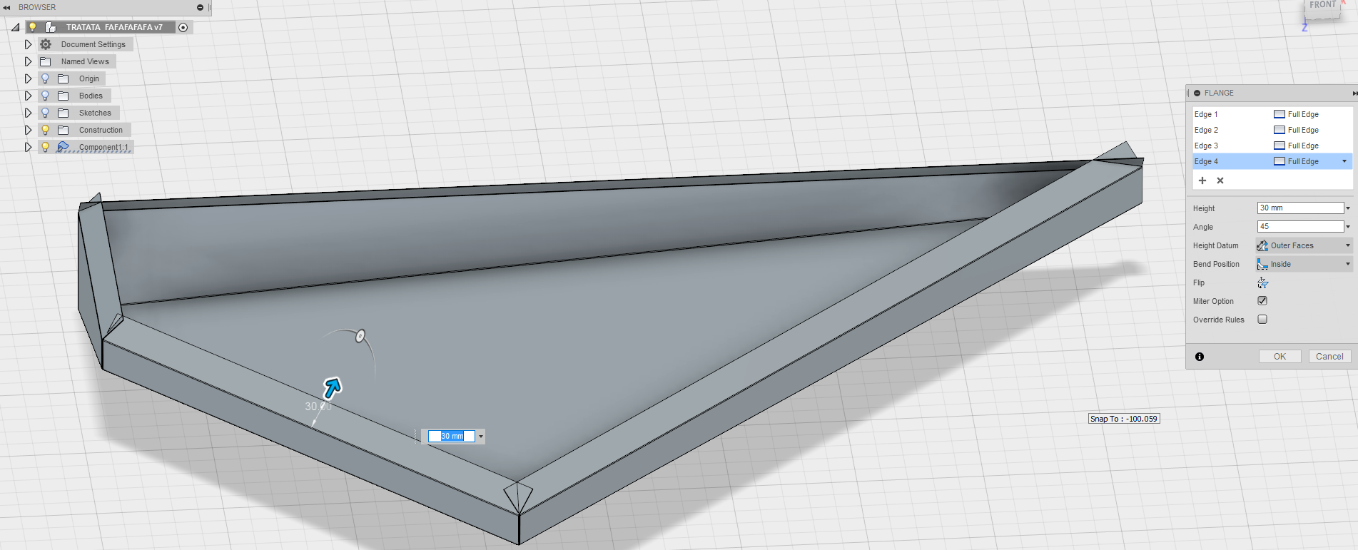
Users are unsure how edit the extent of a flange along a particular edge.
Steel stainless steel and aluminium both in metric and imperial values.
Thickness bend radius k factor relief shapes etc.
Properties are the root of how sheet metal designs behave.
Change is inevitable and a part of life.
Right click on the top component of the design in the browser tree.
So to figure out the thickness you want to use for the material it is useful to refer to a chart of sheet metal specifications.
Your sheet metal manufacturer or supplier should have a document detailing the availability.
A pro version is available if you ever need it which has sheet.
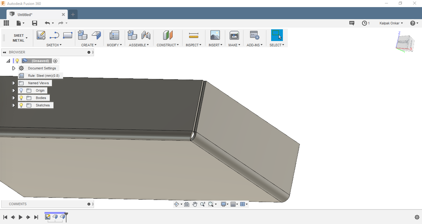
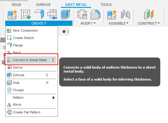
In the new ui the sheet metal environment is located in the tabs above the icons.
We re calling these sheet metal rules in fusion 360.
If sheet metal does not appear there enable parametric modeling mode by capturing design history.
Then i did what any engineer would do jump in head first.
Old user interface prior to august 2019 update.
Sheet metal thickness is typically specified as a gauge rather than a direct measurement as it is presented in fusion 360.
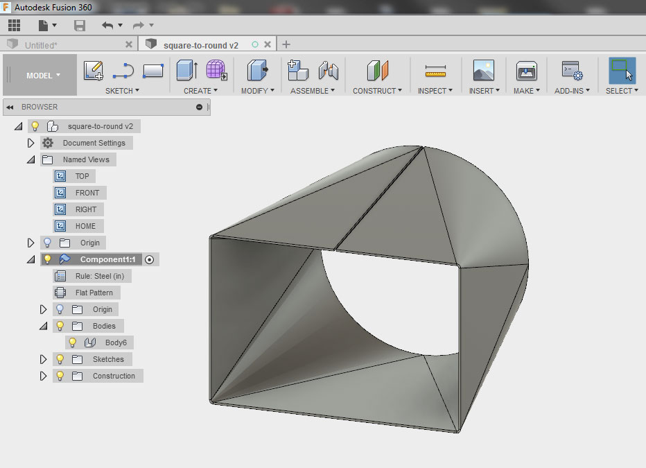
Fusion 360 has all the necessary tools to specify different rules for your sheet metal parts thickness bend radius corner relief etc now here is the fun part actually making some sheet metal.
There is no option to access the sheet metal tab in the fusion 360 design toolbar.
The screencast below details this process.
The default is steel but you can change it to either one of the other rules or you can.
Fusion 360 comes with a default library of sheetmetal rules.
The sheet metal rules in fusion 360 helps control the different sheet metal settings like thickness bend radius and reliefs.


